Installation
Before You Install
Before installing the U by Moen Smart Shower system, it’s important to consider a few key factors such as the number of shower outlets the homeowner intends to use in the shower, valve placement, location of a usable electrical outlet and strength of WiFi signal.

Installation Video
Valve Placement
-
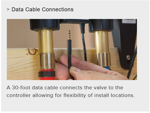
Unlike traditional valves, the U by Moen Smart Shower digital valve does not have to be placed directly behind the shower wall. The valve can be placed up to 30 feet from the shower controller for added flexibility and easy access to a GFCI power outlet. Example of valve between studs.
-
Aside from being connected to a GFCI outlet, the only requirement is that the valve be accessible and not completely closed behind a wall. Options include adding an access panel in the wall to reach the valve or placing the valve in a closet, vanity or other form of accessible cavity. Example of access panel in closet.
-
Risk of Damage to Product: The power supply and valve must not be installed where the ambient temperature can exceed 104 degrees or where freezing can occur.
Electrical Requirements
To determine the correct electrical placement, follow these steps:
|
WARNING: You must determine the location of the valve and electrical supply (GFCI) to allow for adequate slack in the 6-ft. (1.82 m) power cord from the bottom of the valve. A drip loop in the power cord is required at the valve connection. |
- Find the Outlet: Locate electrical outlet above the valve.
- Connect the Circuit: Connect only to circuits protected by a Ground-Fault-Circle Interrupter (GFCI) or an Earth-Leakage Circuit Breaker (ELCB). Grounding is required
|
The 120-volt GFCI electrical outlet should be installed by a licensed electrician. |
- Cable Management: To avoid risk of electrical shock and /or product damage, route power and data cables to avoid contact with hot water supply lines. Power and data cables must also be routed to avoid damage when installing the valve or controller installation screws.
- The valve is supplied in the open position to allow for pressure testing of connections.
Plumbing Requirements
The valve is shipped in the open position allowing the installer to test the plumbing connections with air or water prior to connecting the controller. It’s important to adhere to the following plumbing requirements during installation:
- Plumb outlet A of the valve to the primary showerhead.
- Use dedicated 1/2” supply lines for the S3102 valve and 3/4” supply lines for the S3104 valve.
|
In-line shutoffs are required. |
- Make connections at water inlet and outlet lines flexible enough to allow for valve servicing.
- The valve is supplied in the open position to allow for pressure testing of connections.
|
Note: The controller is not required to test plumbing. |
- Plug any unused outlets.
Water Requirements
Proper U by Moen Smart Shower operation requires the following:
- Minimum incoming temperature of 40°F (5°C).
- Maximum incoming temperature of 149°F (65°C).
- Minimum incoming pressure of 20 psi.
- Maximum incoming pressure of 125 psi.
- Maximum outlet temperature is set to 115°F and cannot be adjusted higher than 120°F.
|
Note: the valve will not allow the user to exceed 120°F. |
-
Water flow rates (at 45 psi): 2-outlet system: max flow of 6 gallons per minute (gpm) per outlet with a system max of 9 gpm. 4-outlet system: max flow of 6 gpm with a system max of 14 gpm.
Typical Vertical Spa Options
There are many different ways a homeowner can configure his/her 2- or 4- outlet U by Moen Smart Shower to create a personalized in-home spa experience. The following diagrams depict three common setups that will appeal to most homeowners, as well as a few options to consider.
|
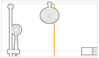
2-Outlet Showerhead This simple setup allows the user to have ideal personalized shower control for a showerhead/hand spray combination. |
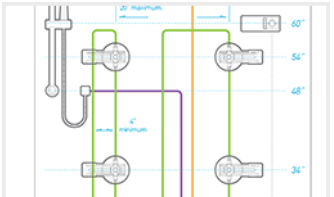
4-Outlet Showerhead, Handshower & Two Sets of Body Sprays: This setup is perfect for homeowners who desire body sprays, which can be placed either in the back wall of the shower or on the two side walls. |
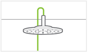
Rain Showerhead, Handshower & One Set of Body Sprays: This configuration offers the ultimate rain shower spa experience by placing a shower head directly above the user. |
Valve Installation and Mounting
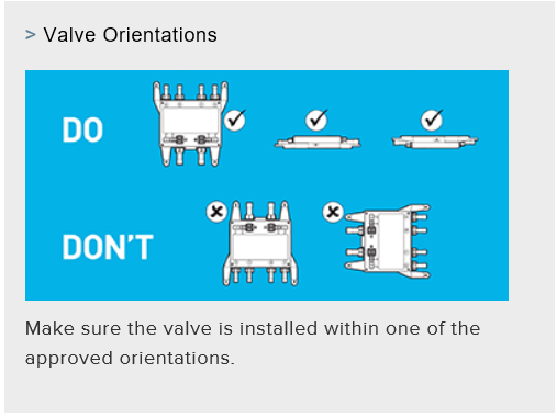
The U by Moen Smart Shower digital valve is installed prior to the wall-mounted controller. Be sure to pay attention to the maximum distance the valve can be installed from the controller as part of the preparation process. Be sure the valve is mounted with the proper orientation. Download Valve Installation Guide
- Prep Valve: Shutoffs are required for installation and/or servicing of shower valve. Turn both shut-off valve handles to the off position.
- Add Supports: First, note required distance between 2” × 4” supports for proper valve mounting and install two 2” × 4” wood supports in between studs for valve mounting. Then secure each support with wood screws (not provided).
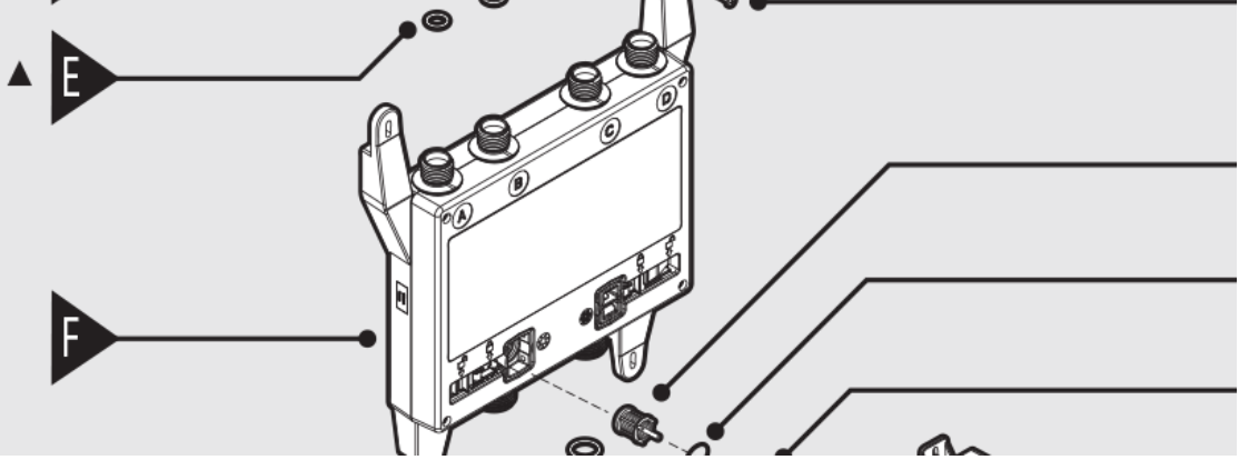
- Mount Valve: Mount shower valve (F) to both wood supports as shown. Shower valve should rest on lower wood support.
- Secure Valve: Use provided shower valve mounting screws (L) to secure shower valve (F); tighten screws.
- Outlet Caps: Remove and discard outlet protective caps (B) from top of shower valve. Then remove and discard inlet protective caps (I) from bottom of shower valve.
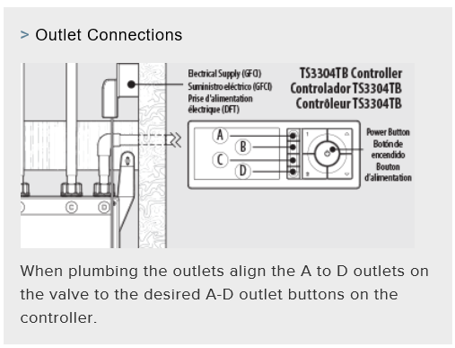
- Connections: Make plumbing connections to inlets and outlets as determined. Plumb outlet A to the primary showerhead.
- Unused Outlets: Plug any unused outlets (outlet cap [A] not included).
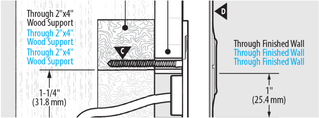
- Controller Support: Identify desired controller location and install a 2” × 4” wood support approximately 60” high for mounting controller. Secure the support with wood screws, then drill a 1¼” hole through the middle. Refer to the diagram for detailed instructions.
- Connecting Data Cable: Note cable connector ends; connect valve end to valve. Guide the data cable (P) through the hole in the wood support. Attach the data cable retainer to the controller end of the data cable to prevent it from falling back into the wall. Insert the other end of the cable into the data port at the bottom of the valve.
- Connecting Power Plug: Plug AC power adapter (K) into AC outlet within wood studs. Ensure that AC power adapter is within 5 ft. (152 cm) of the shower valve (F) and has continuous power. Insert plug into port underneath shower valve.
Controller Installation and Mounting
The U by Moen Smart Shower digital controller mounts easily and connects to the digital valve through a waterproof data cable. A minimum space of 10 x 6 is required for the controller either inside the shower or on an easily accessible wall adjacent to the shower (in-shower is recommended). The controller can only be mounted in the horizontal position. Download Controller Installation Guide
- For controller setup, including language, time zone, water temperature scale and water saving mode, see the How To Use section.
- Be sure to reference the recommended mounting dimensions diagram before beginning to install the controller.
How to Install the Controller:
- Mounting Bracket: Finished wall should have a 1” hole for the data cable. Make sure the data cable (B) has been pulled through the wall with slack and make certain that the data cable doesn’t fall behind the wall. Next, level the mounting bracket (A) on the finished wall and mark drill holes within the bracket. Set mounting bracket (A) aside.
- Mounting Bracket Installation Prep: Drill both marked holes using a 3/16” drill bit.
|
Note: Only drill through finished wall. |
- Mounting Bracket Installation: Apply a bead of silicone caulking within the mounting bracket (A) groove. Adhere bracket to finished wall. Ensure data cable (B) goes through bracket opening. Secure with screws and check that the bracket is level.
- Connect Data Cable: Remove and discard protective cap from data cable (B) and attach cable from controller cable (D) to data cable (B).
- Mount Controller: Feed cabling connection (B & D) back into the wall through the mounting bracket (A). Then attach controller (E) to bracket (A) as shown. Fully engage controller by sliding it down into place. Installation is complete.